The Valve Function is designed for practical process applications. The
complete design incorporates the display of the status on the
WinCC mimic.
It also includes the pop-up template, with detailed display of
the Valve condition, status and properties.
The Step7 function is easily
incorporated into an existing or new PLC project. Details of alarm
configuration will also be supplied.
MIMICS :
Mimic Display : Valve status on-screen need to be discretely small, but with
properties, to display maximum detail. For this purpose we
have designed the on-screen values to reflect not only the Valve condition, but
also the state of the signal, i.e. alarm
condition (red).
The example below shows the three
different states of a Valve: Green - Open, Grey - Closed, Red - Alarm. A typical
diverter valve is also
shown with one direction active(green) and another direction closed(red)
Alarms for Valves are configured to flash on-screen on first occurrence.
This assists with drawing the attention to the problem area. Once
the alarm has been acknowledged, it will stop flashing and change to a steady
state of red.
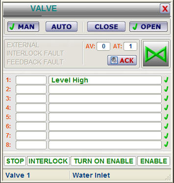
TEMPLATES :
Further information of each Valve will be made available when the operator
clicks on the Valve tag, thereby opening the template
(example) as shown below :
1. Indication that valve is open / closed - taken from open feedback signal in PLC
2. As the template is opened, the correct tag name is displayed,
linking the displayed variable to its associated value. This value
is entered in a DB in the PLC.
3. Template buttons allow the operator to open or close a valve from WinCC (if
he has authorisation).
4. When a new warning, or alarm state occurs, the signal will flash, indicating
an un-acknowledged alarm. Pressing "ACK" on the template will
acknowledge the alarm or warning.
5. Alarm descriptions indicate if there was a failure of an Open or Close signal
Use the ActiveX control below to find out more about the features of this
module :
FEATURES :
VISUAL :
- Allows Control of Valves and Gates in the PLC and for display on WinCC
- Graphical representation of Valve status
- Alarming can be enabled / disabled from the PLC for both open and closed
feedbacks
- Visual confirmation of tag name on display
- Visual representation of alarm
- Mimic and template will visually indicate a new or acknowledged alarm
PLC :
- Multiple Valve entries into one datablock possible, i.e. doesn't
require a DB for each measurement
- Addressing is done directly to Valve I/O, e.g. I23.7, Q25.3
- Various Valve types supported, Open / Close Valve or Gate, Diverter
Gate, also dual solenoid Valve
- Configurable time-out value for feedback alarm
- Alarming can be enabled / disabled from the PLC
- Valve can be controlled open/close from PLC software
WHAT IS INCLUDED :
The Valve package includes the following :
WinCC :
Full step-by-step configuration and instruction manual.
Example mimic with Valve implementation
Usable Mimic display items. (copy/paste from example)
Structure tags in WinCC
Pop-up template (as WinCC .pdl files)
Step7 :
Full step-by-step instruction manual.
Example function and datablock with Valve implementation
Structured tag (UDT) for creating new datablocks
Valve Function (FC) for use in programming.