The Digital Alarm Function is designed for practical process applications.
Although measuring an alarm on a single digital input sounds simple,
the combination of monitoring various states of the signal, filtering out noise,
and providing a useful operator interface is slightly more complex.
The
complete design incorporates the display of the signal status on the WinCC mimic.
It also includes the pop-up template, with a display of
the signal/alarm condition. The Step7 function is easily
incorporated into an existing or new PLC project. Details of alarm
configuration will also be supplied.
MIMICS :
Mimic Display : Digital alarm signals on-screen need to be discretely small, but with
properties, to generate maximum effect. For this purpose we
have designed the on-screen display to be as user friendly as possible.
Alarms and warnings are configured to flash on-screen on first occurrence.
This assists with drawing the attention to the problem area. Once
the alarm has been acknowledged, it will stop flashing and change to a steady
state of red (alarm still present) or green (healthy state). The alarm
will hold its state until acknowledged, ensuring no alarms are lost while not
being monitored.
TEMPLATES :
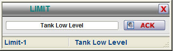
Further information of each value will be made available when the operator
clicks on the tag of the digital alarm, thereby opening the template
(example) as shown below :
1. As the template is opened, the correct tag name is displayed in this field,
linking the displayed variable to its associated value. This value
is entered in a WinCC field.
2. When a new alarm state occurs, the signal will flash, indicating
an un-acknowledged alarm. Pressing "ACK" on the template will
acknowledge the alarm.
3. This coloured bar indicates the state of the signal - grey (healthy),
flashing red (new, unacknowledged alarm), static red (acknowledged alarm)
Use the ActiveX control below to find out more about the features of this
module :
FEATURES :
VISUAL :
- Visual confirmation of tag name on display
- Visual representation of alarm state
- Mimic and template will visually indicate a new or acknowledged alarm
PLC :
- Multiple measurement entries into one datablock possible, i.e. doesn't
require a DB for each signal
- Addressing is done directly to digital input, e.g. I124.3
- Configurable "healthy" state for each signal, allowing use of signals
that are healthy ON or OFF
- Alarm filtering possible, allowing time delays to filter out unwanted
alarms
- Alarming can be enabled / disabled from the PLC, e.g. only measure the
flow switch if the pump is on.
WHAT IS INCLUDED :
The Digital Alarm package includes the following :
WinCC :
Full step-by-step configuration and instruction manual.
Example mimic with Digital Alarm implementation
Usable Mimic display items. (copy/paste from example)
Structure tags in WinCC
Pop-up template (as WinCC .pdl files)
Step7 :
Full step-by-step instruction manual.
Example function and datablock with Digital Alarm implementation
Structured tag (UDT) for creating new datablocks
Digital Alarm Function (FC) for use in programming.